This page explains what I did in much more detail for those who want to build a lapstrake dinghy but who – like me – have only limited woodworking experience and few of the specialist tools that the boatbuilding books illustrate. Experts are perfectly entitled to wince at the way I did it, and probably will.
It was a tremendous help to be offered the use of the well-equipped workshop of our next door neighbour, Paul Broomhead, whose cutting, drilling and shaping machinery was a boon. His chisels and planes were also an awful lot sharper than mine.
I’ve built a lapstrake dinghy before, but it was exceptionally simple, a Barrowboat, which paradoxically relied on inaccurate fitting of the planks for its strength. When set up on the mould, with the planks lightly screwed together, there was no need to bevel them, thus creating deliberate gaps between the edges of the planks into which thickened epoxy glue was syringed to make a bond. It produced a strong hull, but a lot of glue showed. The Barrowboat also came with all the parts formed, whereas my kit was just planks, moulds and transoms, with everything else to be made from scratch.
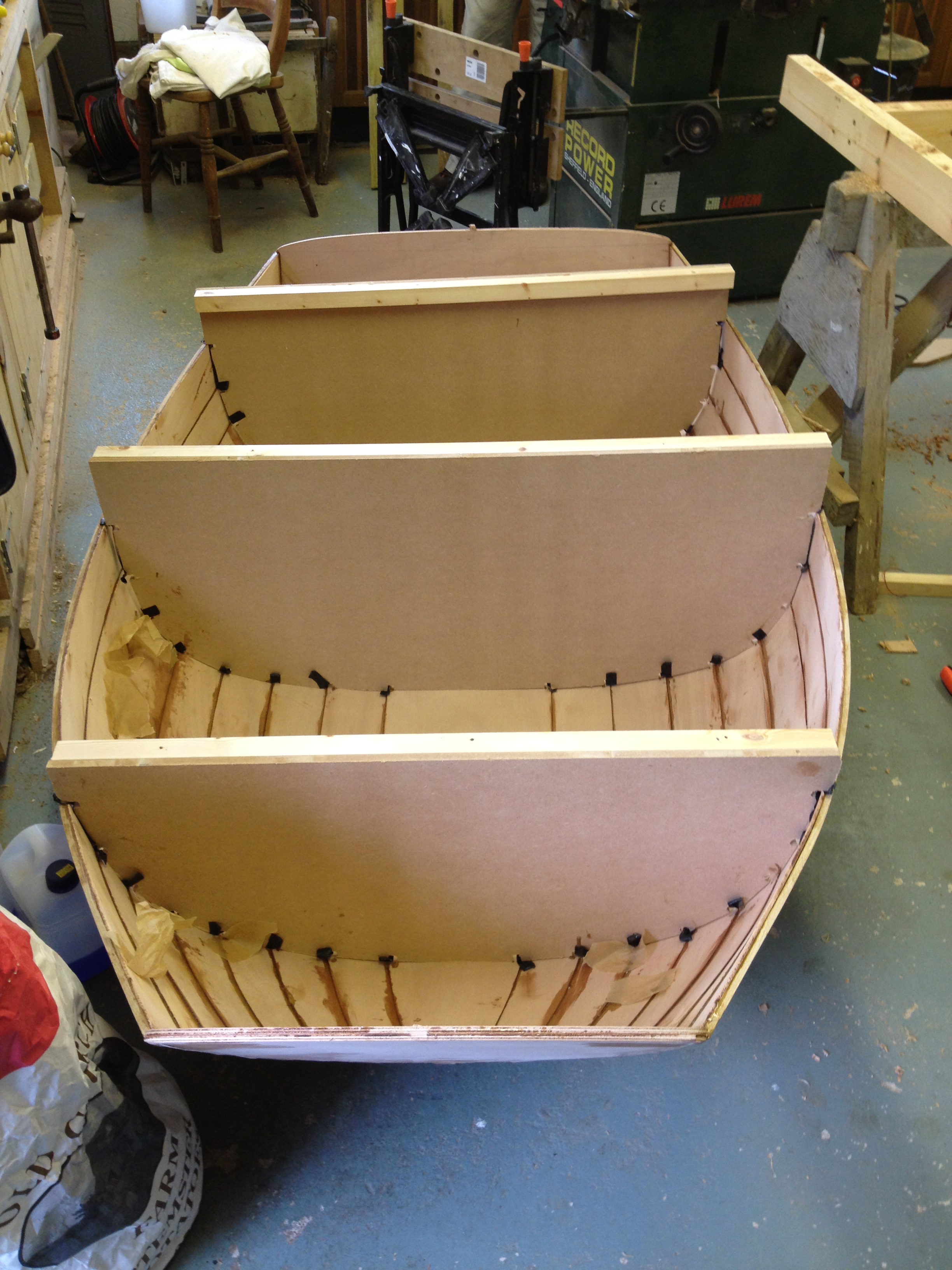
Setting up the Feather pram moulds:
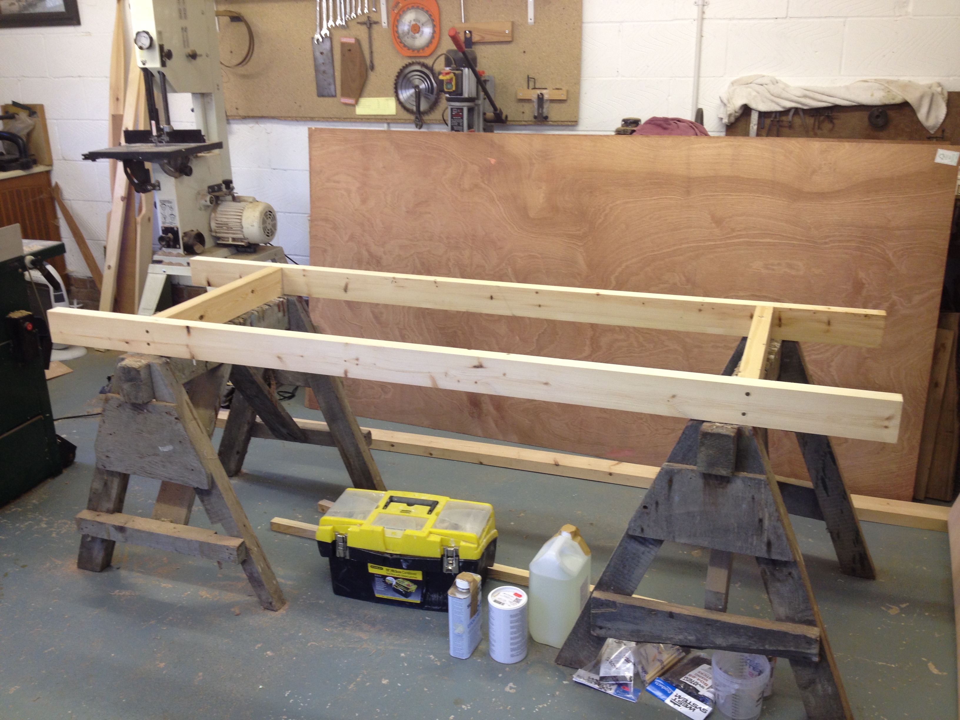
The frame was made using planed timber from the builder’s merchant, and the timber was not exactly straight. To deal with this, the centre line was set up first between the main timbers. Using this line a pair of parallel lines were drawn, one on each of the timbers. From that stage on, it didn’t matter that the timbers were not straight.
The positions of the ‘stations’ (the basic reference points) from the plan were measured and marked on one of the parallel lines drawn on the timbers. Using diagonal measurements from fixed points on the centre line, the position of the equivalent station on the other timber was marked. The line between these two points was the station line. There were seven of these altogether
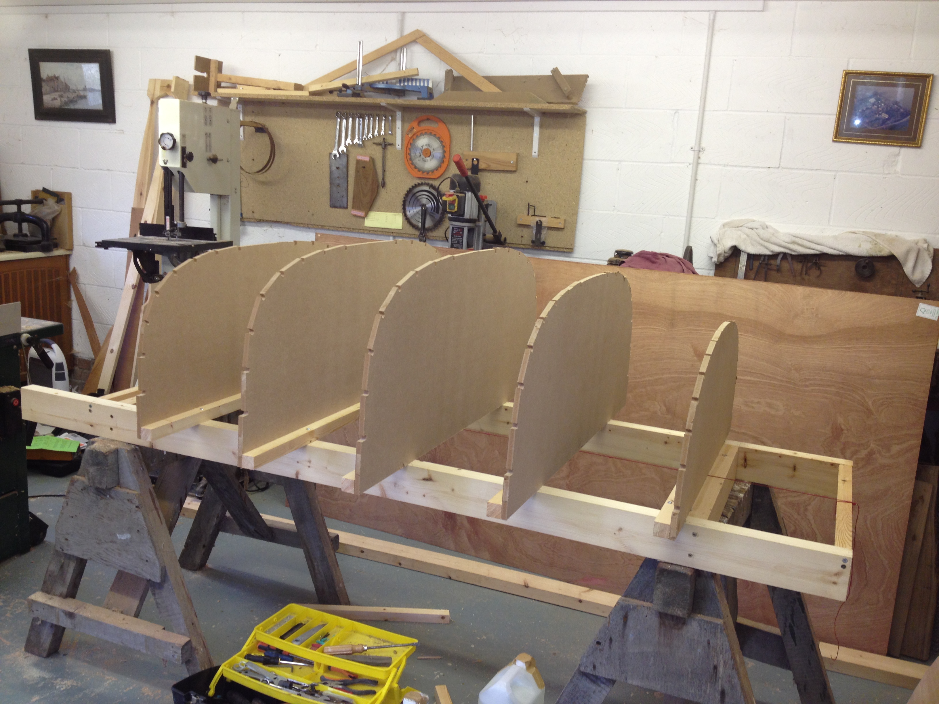
This geometry theoretically ensured that the station lines were at right angles to the centre line, though it took a couple of goes before successive measurements began to agree to a millimetre or so. The mould positions were then marked from the station lines as in the plans. Note that they are not all on the same side of the station lines.
With the moulds set up, I used the templates provided with the kit to fix the two transoms at the correct angles and correct positions in relation to their stations. This was the fiddliest part of the process.
The design drawing says the moulds should be set vertically, using battens to hold them. This didn’t work out exactly. I checked and rechecked the positions of the moulds against the design drawing and was pretty confident that they were right. However, the planks come with small holes drilled to mark the positions of the moulds, and when I fitted the bottom and the first pair of the planks, only one of the moulds proved to be exactly vertical under the holes. I decided to go with the marks on the planks, and abandoned attempts to set up the moulds exactly vertical. It worked fine until the last two planks each side, when the three moulds most out of vertical were no longer coinciding with the plank marks at all. Not sure what the solution is, but my setting up measurements were probably not as accurate as I thought. In the end, it did not make any obvious difference to the shape of the boat.
Fastenings:
The plans and accompanying notes include a long list of expensive bronze screws and nails, and stainless steel is suggested as a fallback. It is supposed to be possible to complete the boat with hardly any fastenings, using clamps, but it does help eg to screw both ends of the planks to their respective transoms when gluing. In the end, I used cheap brass screws on the grounds that if the boat could be all glued, then weaker screws would be fine, and once embedded in epoxy they should stay corrosion free. For the initial positioning at the aft end, I also used cheap steel panel pins, and replaced them with screws when the plank was properly positioned. Brass and steel proved a mistake, because several of pins and screws stuck fast in the epoxy and broke, so I sealed them in with epoxy to prevent corrosion.
Stainless steel screws are used anyway for strength on larger fittings later such as the skeg and if I did the jobagain I would use only stainless for everything, including the temporary fastenings.
Clamps:
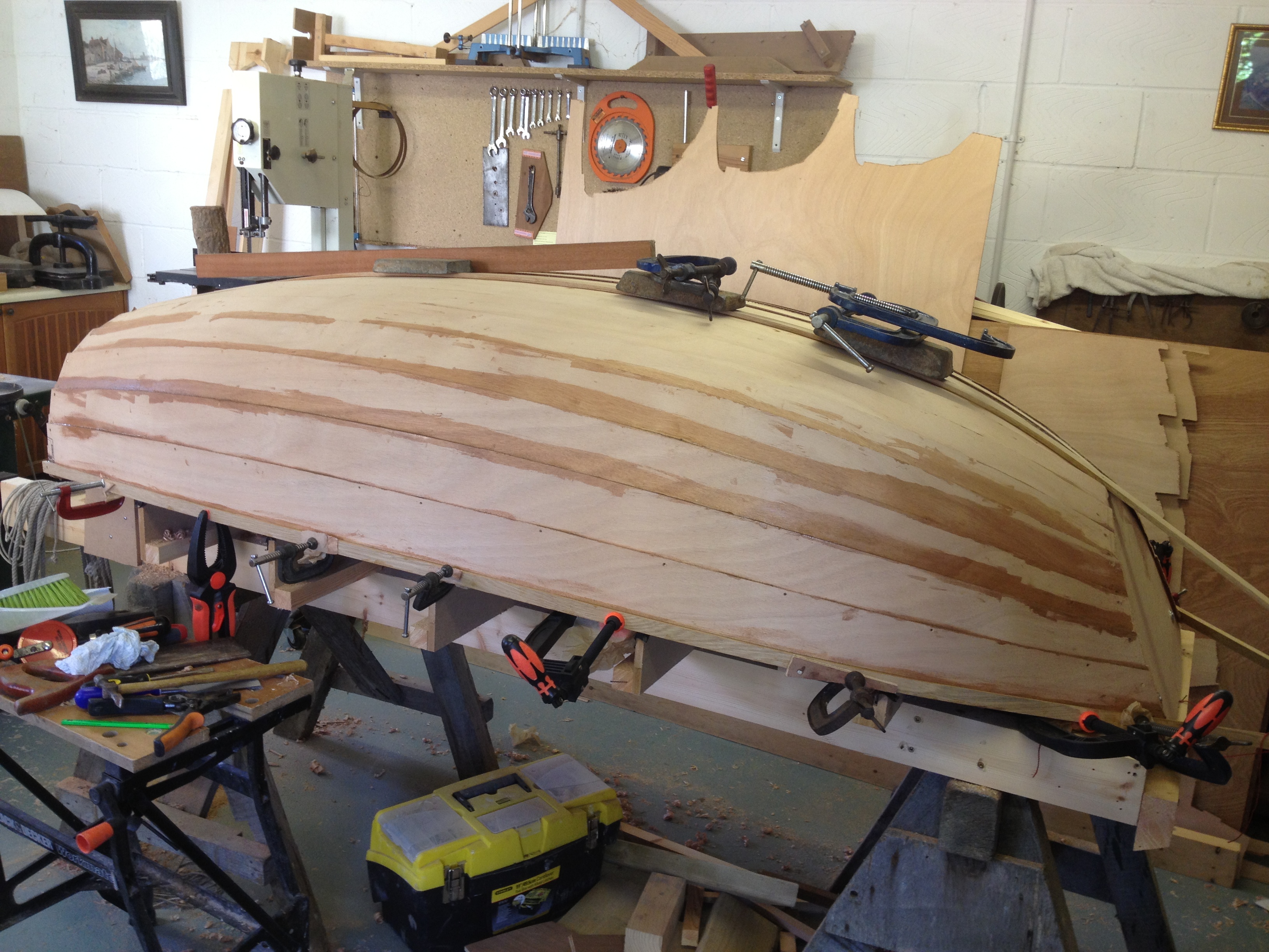
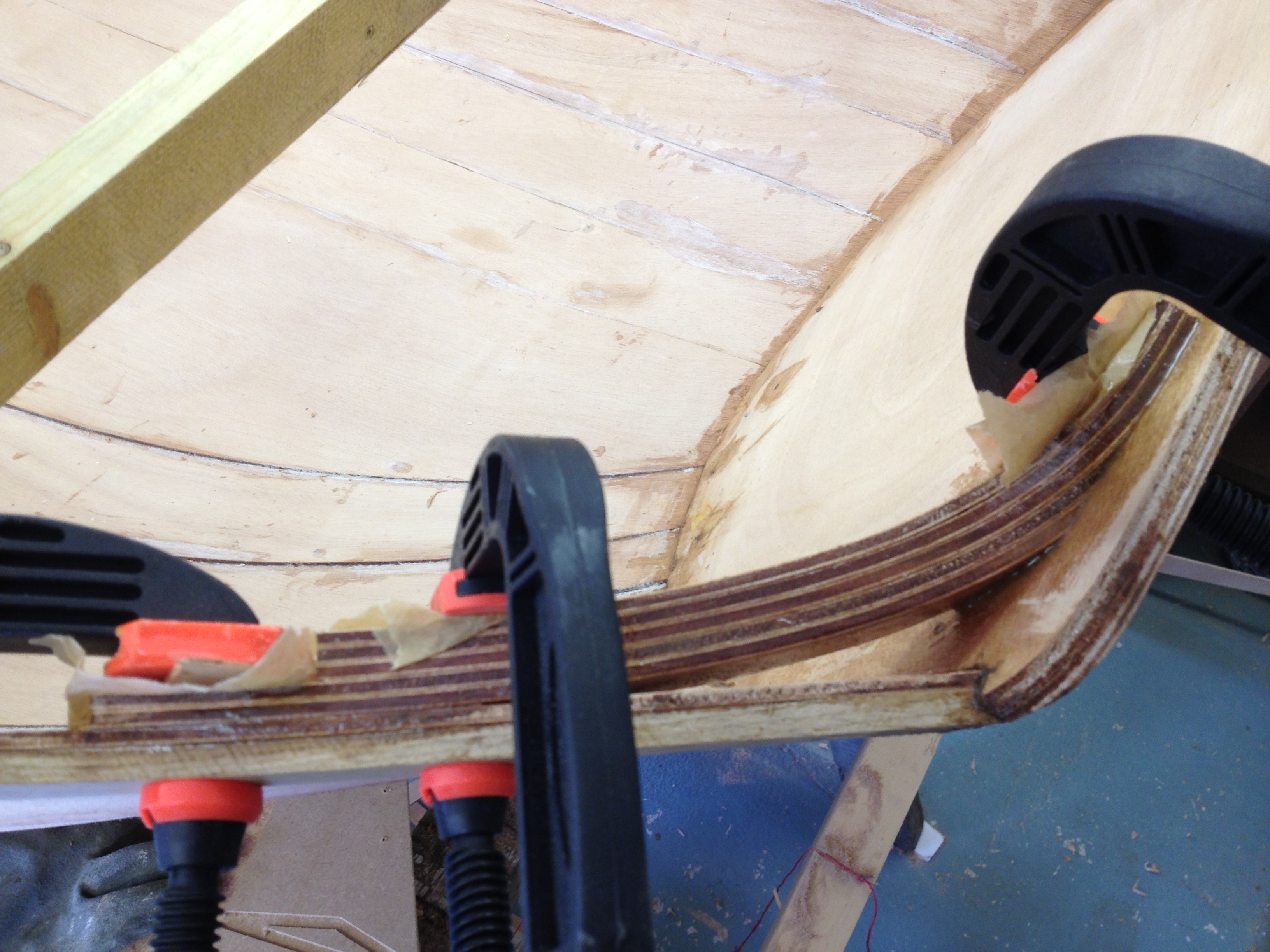
These were a big problem because so many are needed to make a closely glued plank joint (after bevelling the edges to fit). Illustrations showed special boatbuilding clamps, which are very deep, allowing them to fit over the width of a plank and press down on the joint. It seems that most boatbuilders make their own, but I found I needed about 10 clamps per plank and wanted to fit two planks a day. The thought of making 20 fiddly clamps from scratch was offputting. Much the same shape clamps are available to buy on line, for boatbuilding and cabinet making, but a set of 20 would have cost half the price of the kit.
So I made do with the ordinary C and G clamps we have, plus a couple of pincer-type sprung clamps for quick positioning where the planks were narrow.
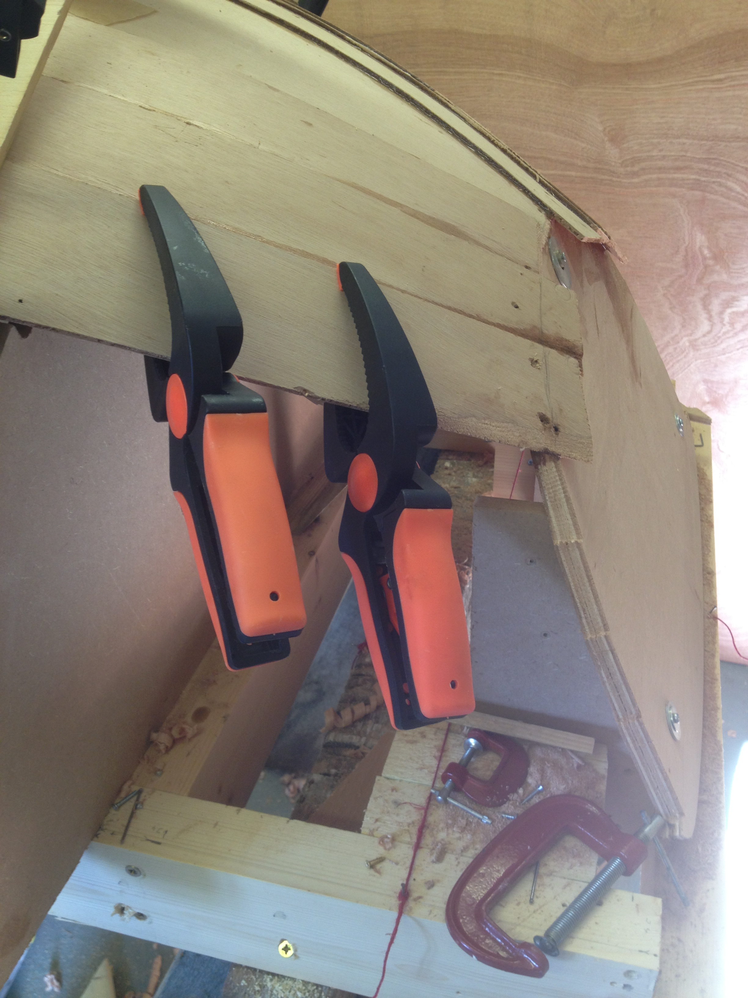
Ordinary clamps fitted completely over the glued joints where the planks were narrow, so the perfect pressure could be easily achieved there. I used small wooden blocks to stop the clamps marking the wood (except for our plastic clamps, which were less brutal on the wood) and wherever there was a risk of glue sticking to the clamps and wood I masked it with greaseproof baking parchment, which came away easily from the set epoxy.

However, the clamps weren’t wide enough along most of the length of the planks. So in desperation (regretting not having made some proper clamps) I set up a Heath Robinson looking apparatus – clamping long, thin thin pieces of wood to the planks and then weighting the end of each piece of wood, to transfer the pressure upwards to the glued joint. By carefully judging the weights (bits of scrap wood and spare clamps) it was possible to fine tune the pressure on the joint so that it fitted exactly.
There was, however, a tendency for the other side of the plank to lift, so I nailed that temporarily to the mould through the marker holes that Jordan Boats had drilled on them. When I got to the side planks, with the clamped sticks of wood nearly vertical, I used string instead of weights to tension them.
Though this ramshackle method worked, with hindsight it would actually have been worth spending the time to make up 15 or 20 specialised clamps with wedges, as shown in the illustration – but that’s for the next time!
With the later planks, I experimented with small (half inch) screws instead of some of the clamps, and this actually pulled the joints together far more effectively, expelling an even bead of glue along the edge. The downside is that the holes have to be filled, either with wooden plugs (for the varnishing perfectionist) or epoxy mixed with fine sawdust, in our case. The last two planks I did entirely with screws at one foot intervals and they fitted better than any previous ones, but there were rather a lot of holes to fill later (not in fact a problem if you are painting the hull). I used whatever half inch screws I had – some brass, some stainless – but the latter are a safer bet, because sometimes the epoxy grips the brass so well that there is a risk of the heads coming off when unscrewing. If I ever build another lapstrake boat, I’ll use screws much more than clamps, as I did years ago with the Barrowboat.
Glue:
I used West Epoxy 105 resin with the less common 207 hardener, which is added one to three instead of one to five, using the calibrated pumps the company sells with its glues. (There is a special one for this hardener). The advantage is that a thin coating behaves and looks much the same as an epoxy varnish, so spillages and wipe marks don’t spoil a varnish finish to the boat. I also used 405 filler to thicken it, which allows the glue to fill substantial gaps without losing much strength.
An expert would probably make such perfect joints between planks with accurate bevels that only a thin layer of clear glue would be needed. Learning from Barrowboat experience, I used thickened epoxy instead, and increased clamping (and screw) pressure to the point at which a bead was expelled along the joints, which could be smoothed with a gloved finger or the end of a plastic mixing stick. The idea was that once this happened any gaps from irregular bevelling would have been filled by thickened glue, which makes a very strong joint on its own. Any surplus is wiped off. The West website, which has a lot of helpful advice and examples plus links to boatbuilding sites, recommends priming both the bare surfaces with unthickened glue first, to soak into the grain, followed by a layer of thickened glue on one surface only.
The other advantage of the hardener I chose is that it is slower setting, so I had an hour to work the planks. A disadvantage is that there was such a long wait – 12 to 15 hours – for the glue to harden that it limited the number of planks that could be done in a day to one or two and prevented other jobs being done on the hull while the glue was soft (as did my awkward workaround for the clamps, because the weights could easily be knocked off). Planking was single handed.
Using the transparent 207 hardener, any spillages could be brushed out like a varnish. I also brushed epoxy along the edges of the planks to seal the ply. Later I used a flat plastic mixing stick to push thickened epoxy as a filler between the plank edges , so there were no dips that would hold water when the boat is stored upside down in the winter.
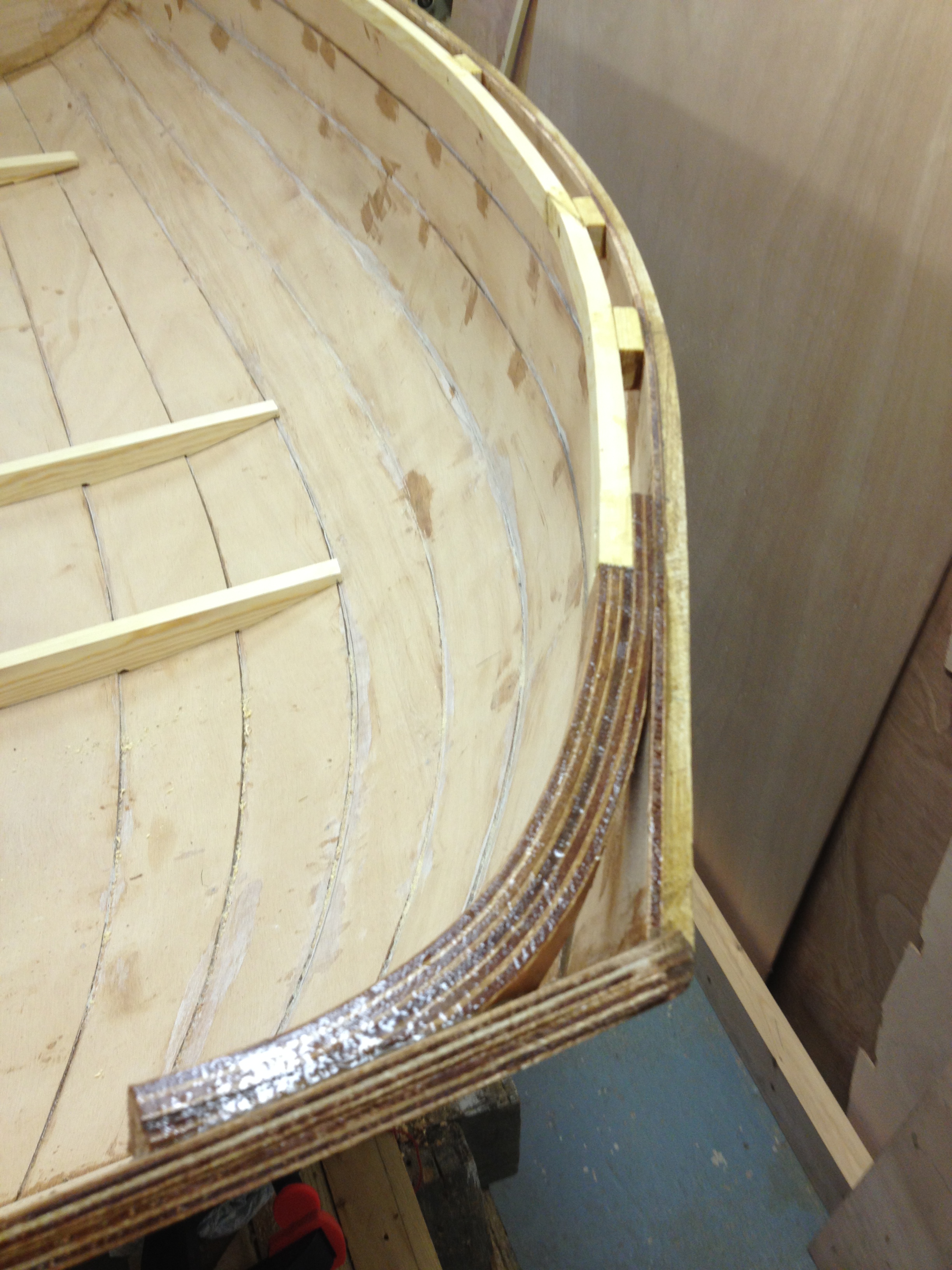
Rubbing strakes, keel and skeg:
The strakes and keel were made from light oak stripwood bought from the joinery mouldings section of the local builders merchant. One standard 10 x 30 mm x 2.4m length was more than enough for each piece.
The keel was laminated in situ from two pieces of the stripwood, screwed at either end. Lead weights helped flatten it to the hull. The rubbing strakes were clamped and screwed, after trimming to size with a circular saw.
The skeg was made in two pieces from a piece of old mahogany furniture. One piece was shaped by resting it on the bottom plank and drawing a pencil line along the curve of the keel. The curve was cut with the jigsaw. It wasn’t deep enough so another piece of the mahogany was cut to a triangular shape and glued on top. No screws were used at this stage – it was easier to get the skeg exactly vertical without them. When I turn the boat over I will put a plywood backing pad (not on the plan) and then two long screws into the skeg to reinforce it against sideways knocks, because otherwise it will be no stronger than the top veneer of the plywood plank to which the keel pieces are glued.
Knees:
Paul Broomhead showed me how to make a mould for laminating the knees. He photocopied the plans, cut out the full-size shapes of the knees from the photocopy and drew the shapes onto foot-long pieces of scrap 3 inch builders’ timber. He used his jigsaw to cut out the shapes from the timber, and made notches on the back to hold clamps – see photos – and then we cut strips 25 mm wide of left over planking ply, using the circular saw.
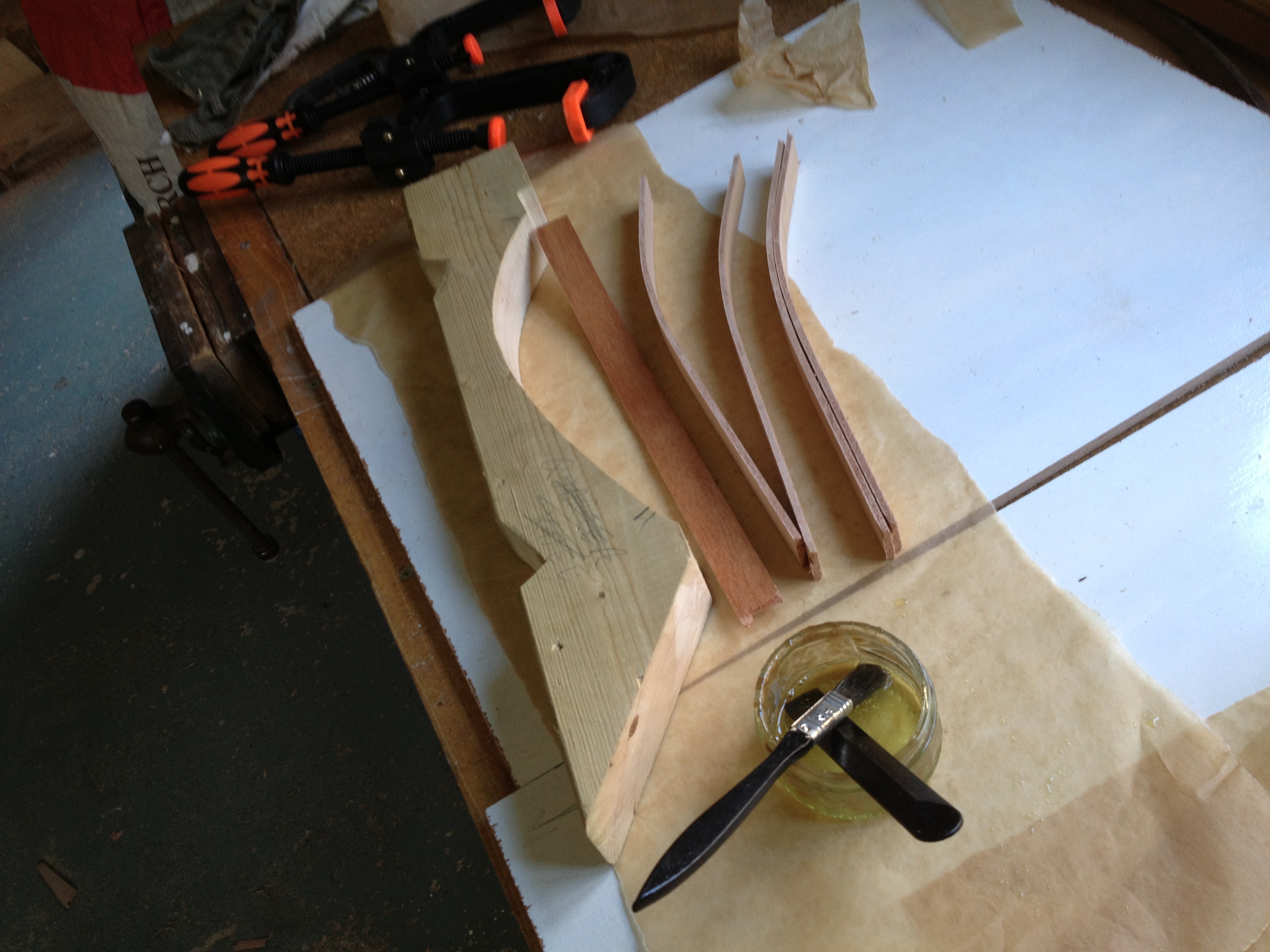
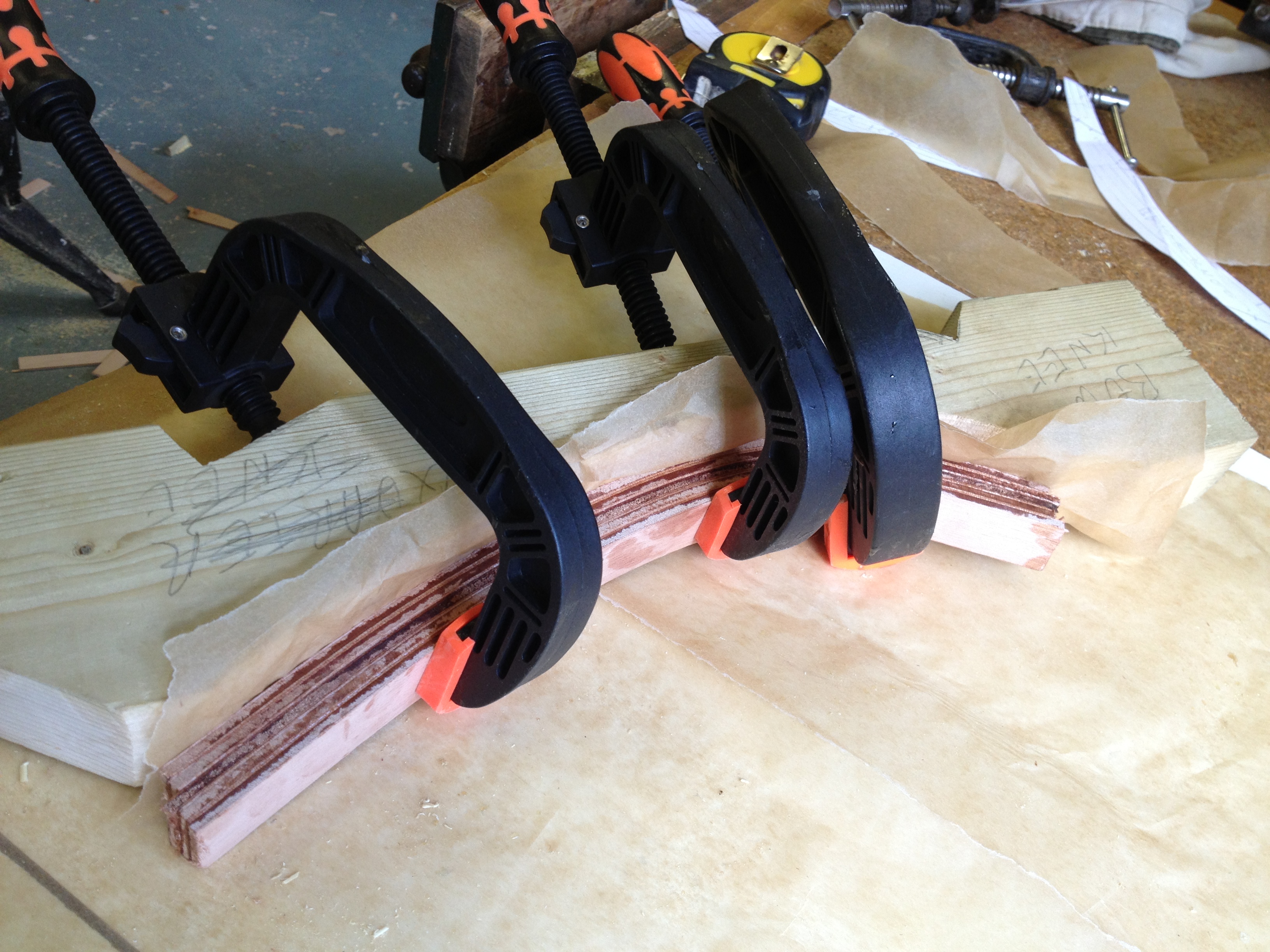
Under Paul’s tuition, I cut these into short lengths and bent them into the mould without glue, and clamped them into position. Even a few minutes left in the mould like this made them easier to handle. Then I made up the glue, took the pieces apart again, applied the glue, and squeezed the laminations together until they were tight against the mould, tapping them at the sides to make sure they were lined up one on top of the other. I used baking paper to stop the bottom laminate sticking to the mould, and gave them a full 24 hours to harden before taking the knees out and trimming them.
Three pairs of knees were made – two each for bow and stern and two to hold up the thwart.
Fitting them, after the boat was turned upright, was tricky: although measurements were enough to get the angles roughly right, the joining surfaces then had to be cut back with a plane little at a time, judging by eye how far to go and offering them up very frequently. Somehow it worked. They were clamped and glued, and screwed later for reinforcement.
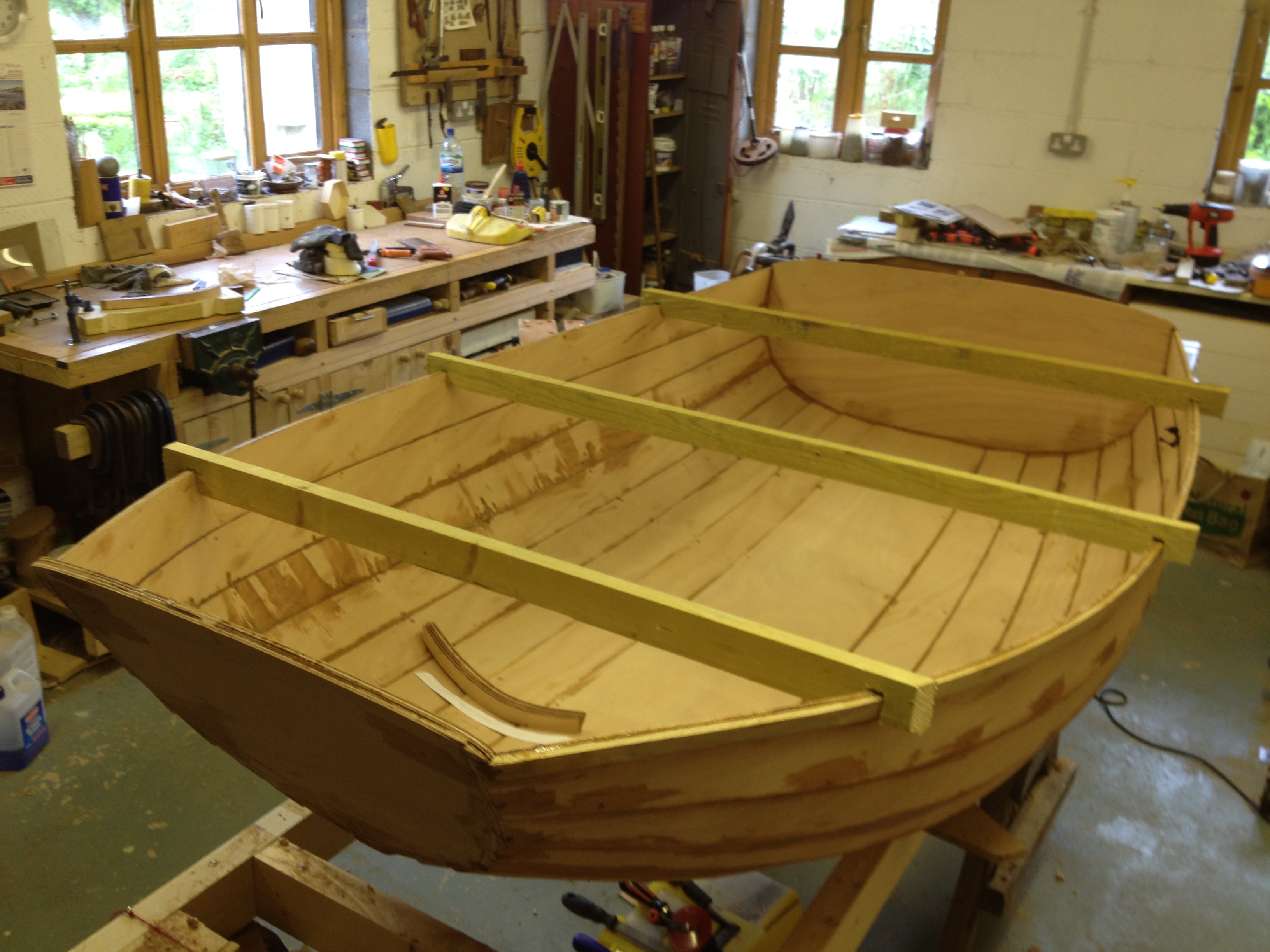
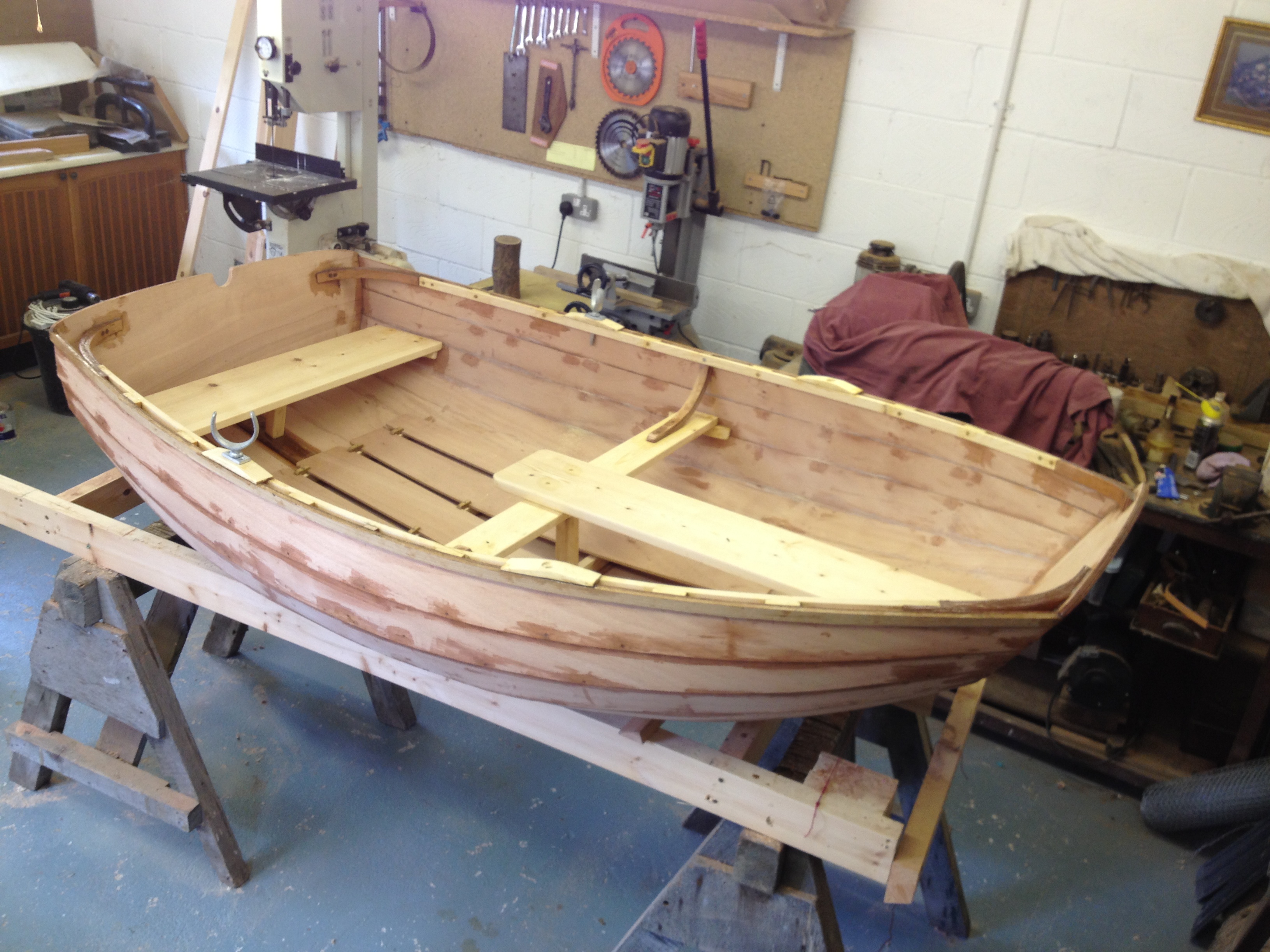
Fitting out the inside:
Apart from the spacers on the gunwale, all the rest of the parts were made, fitted and screwed in place, then taken apart and glued in one single operation at the end.
The gunwale and spacers were made from planed softwood, and like the rubbing strakes and keel were bought from a builder’s merchant. The gunwales were tricky to fit, even when cut into two pieces and scarphed, because they needed to be both twisted and bent. This was the only part of the job in which the epoxy glue failed, when several of the previously-glued spacers parted company with the top plank as the gunwale was being fitted, probably because the clamps hadn’t held them flat enough against the ply. So screws were used as well, through the gunwale and spacers, and into the oak rubbing strake on the outside. After that it was a very solid assembly.
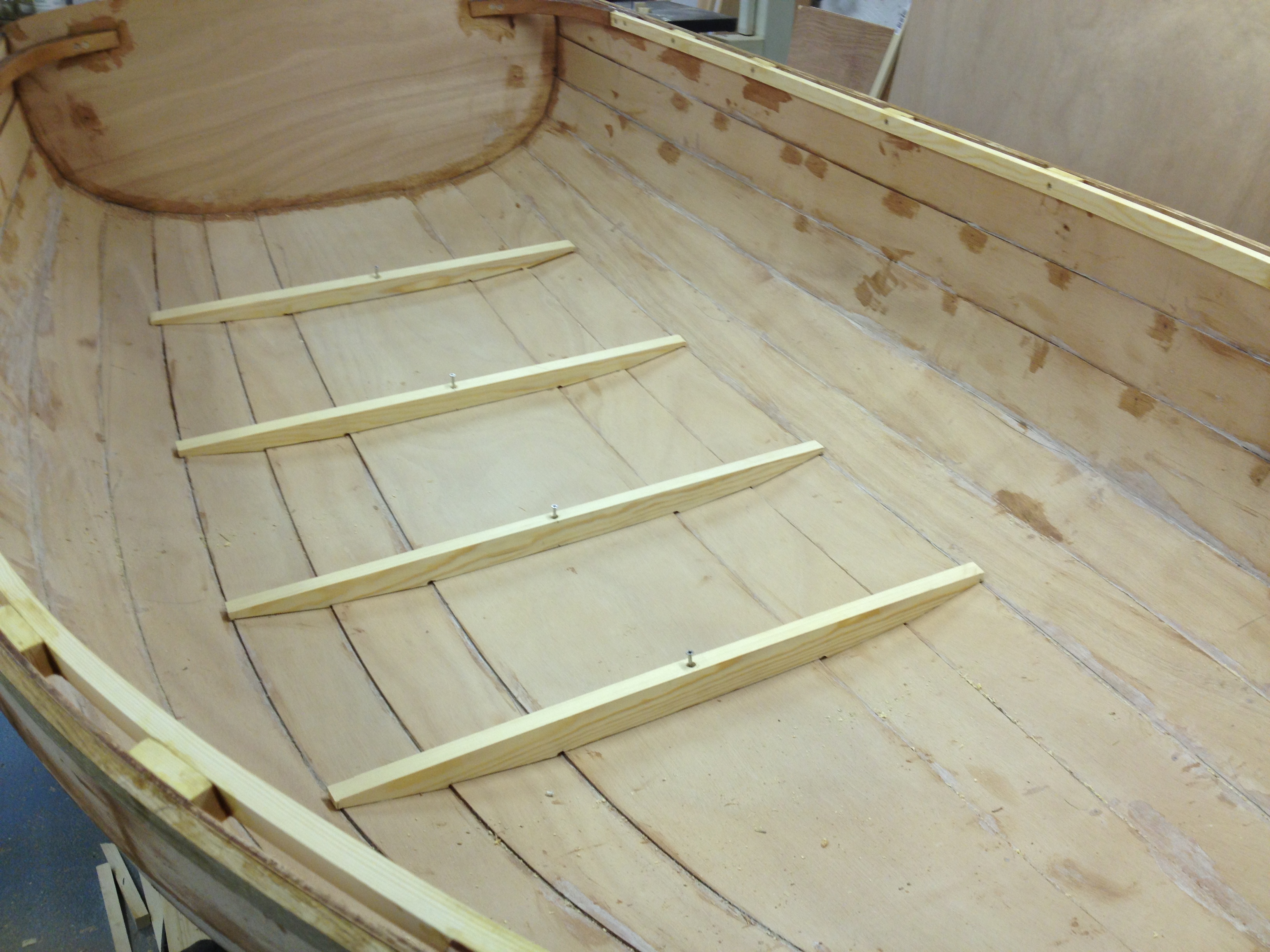
Next, the floors were fitted, with builders’ merchant’s planed pine, cut roughly to shape by measurement and then scribed with a pencil and a short flat piece of wood. They were fixed with a single screw through into the oak keel.
The beam, stern thwart and bench were also made from planed pine from the builders’ merchant, after abandoning a plan to laminate them from leftover ply, because of the amount of epoxy required (by this time we were running short).
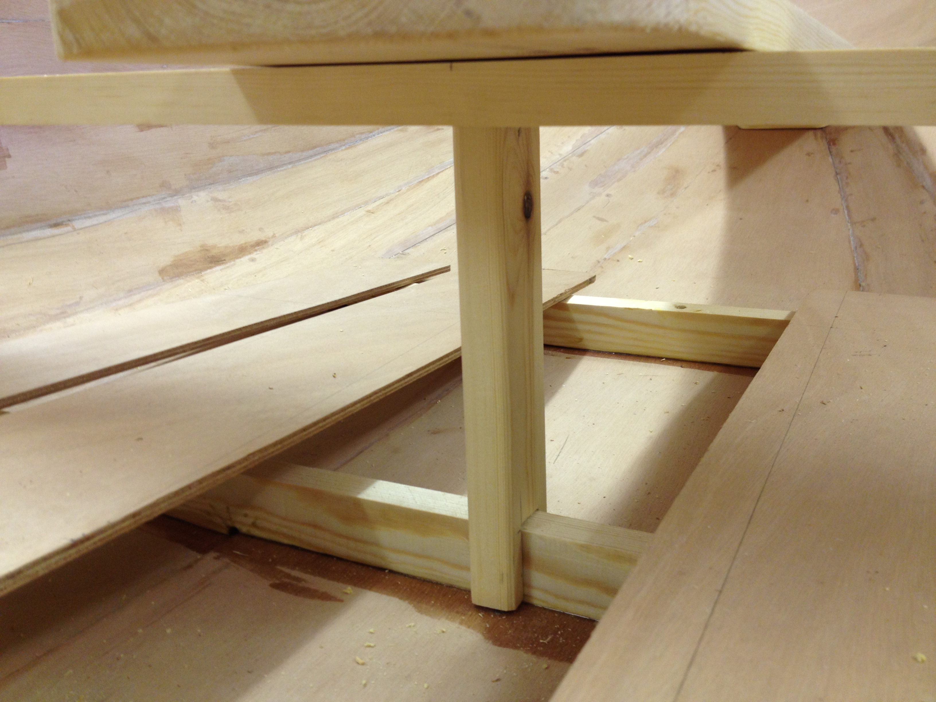
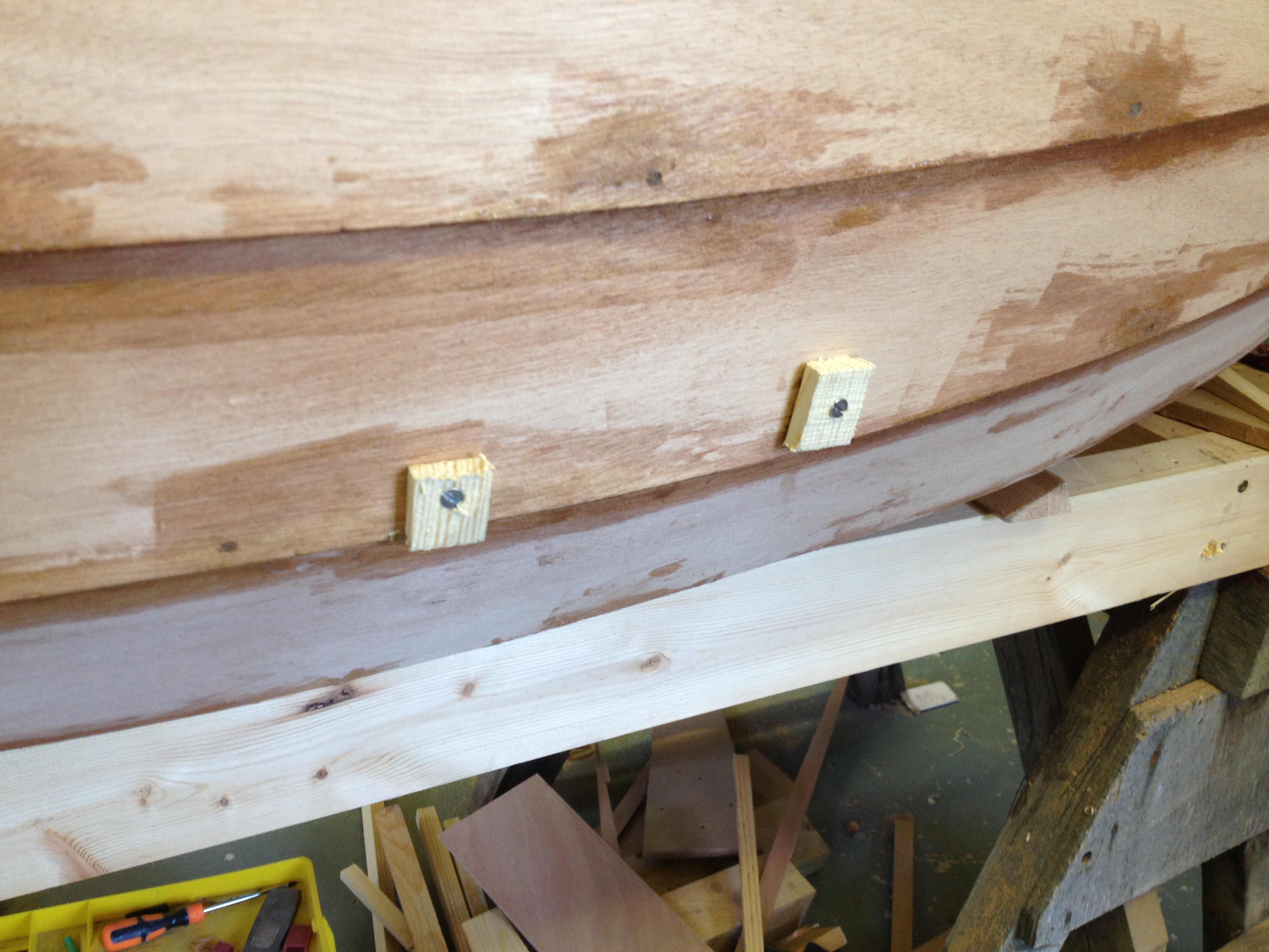
I added short stanchions under the beam and the stern thwart as extra support, because the design, while elegant, didn’t look strong enough to take a large adult: it uses cleats glued to the inside surface of the planks and – as we found with the gunwale spacers – if the joint isn’t made perfectly there’s a potential weakness. The cleats were fixed while the glue set with temporary screws, using small pieces of wood as washers to stop the screwheads digging into the planks.
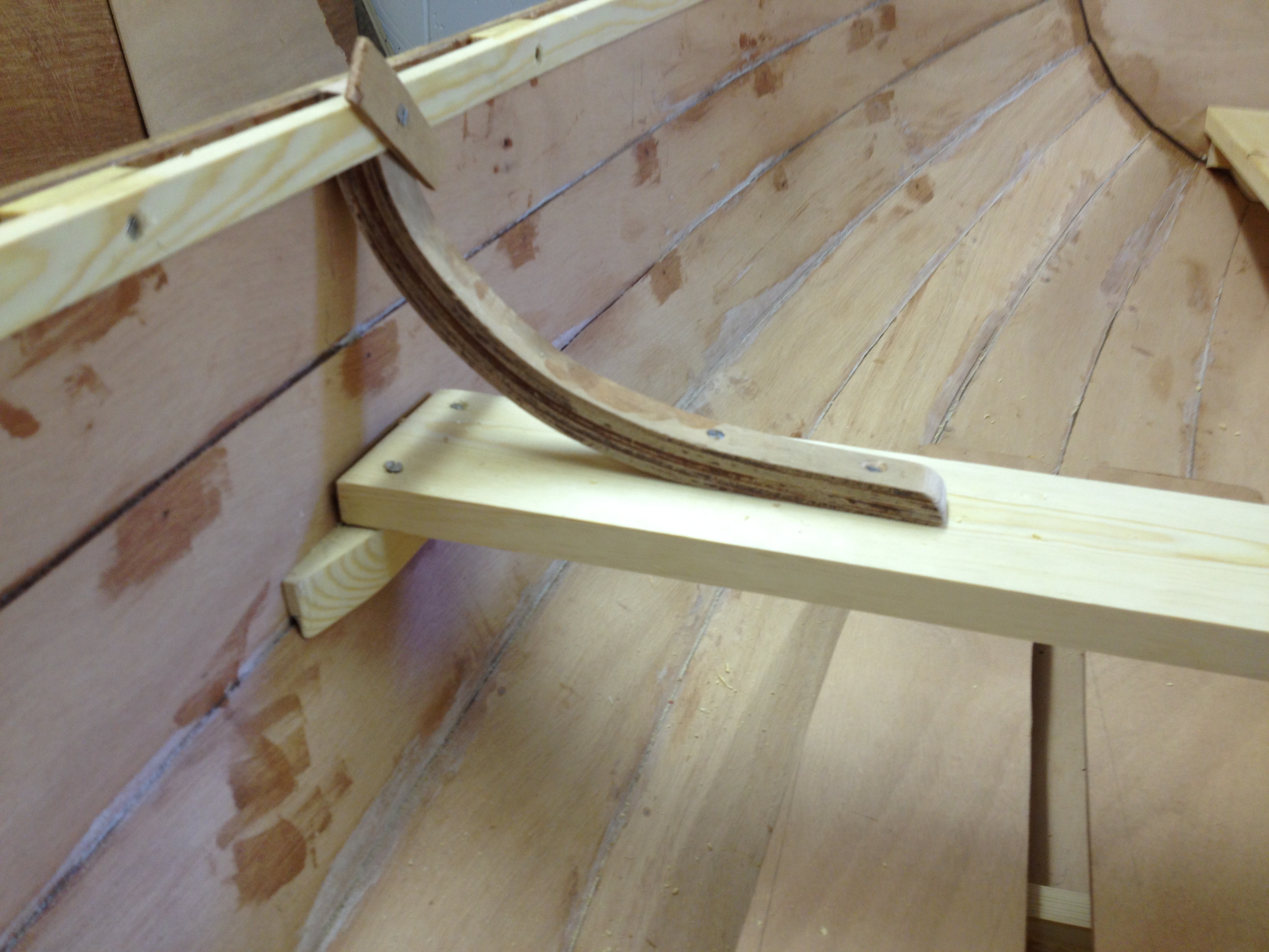

The two previously-moulded knees supporting the beam looked complicated to fit but actually turned out to be surprisingly easy, after holding them roughly in place and marking cuts, finishing the surfaces to be glued with a plane.
Next, the bottom boards were made from leftover quarter inch ply (the rest of the sheet used to laminate the two transoms) which is thinner than the softwood suggested on the plans but seems strong enough. Rectangles were cut out using measurements from the plan, then the curves were drawn in pencil and cut out with a jig saw.
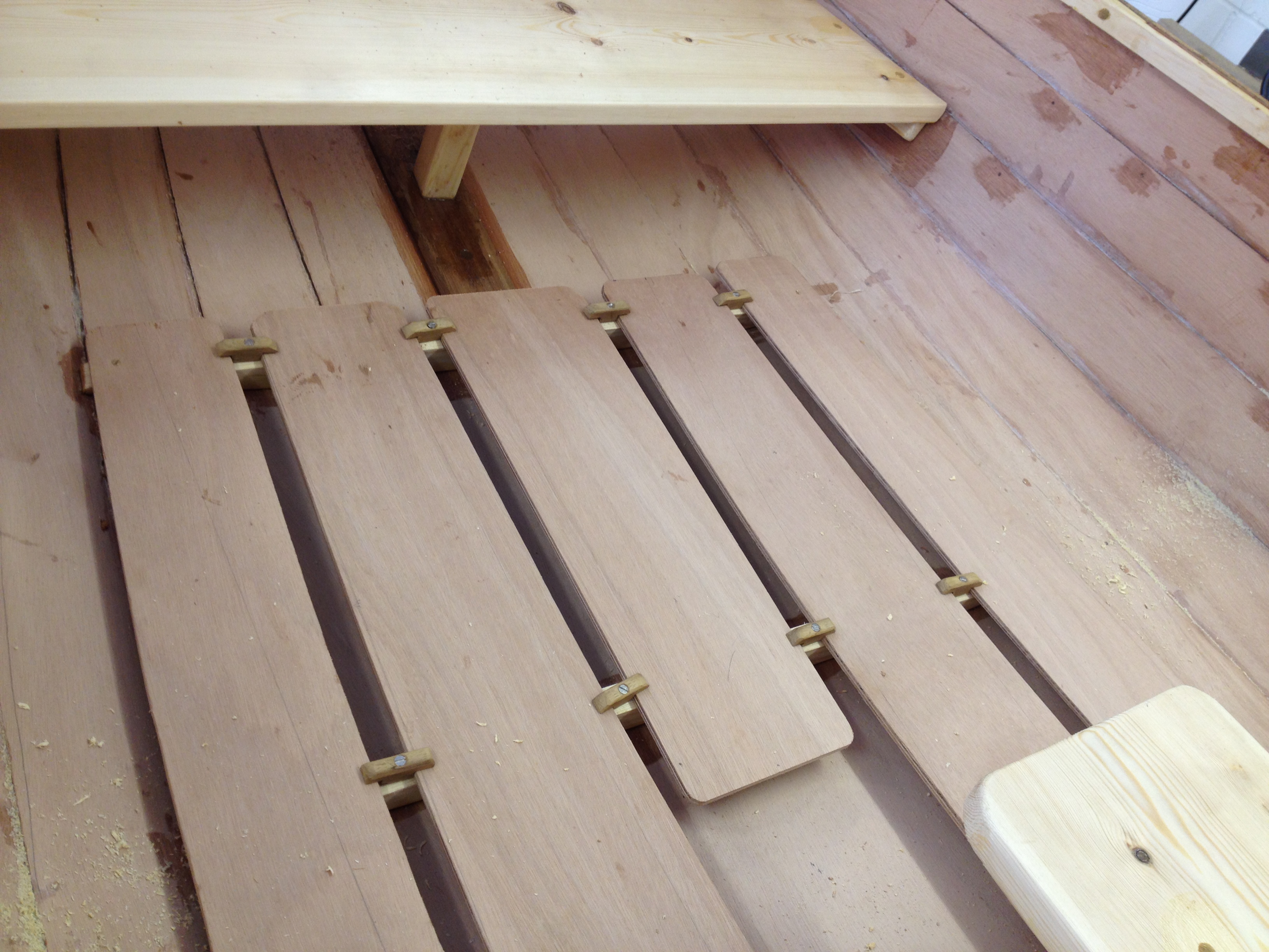
The toggles for holding down the boards were made from a spare piece of iroko, cut with a tenon saw and rounded by holding them against a power sander. All the pieces made in this latest stage were then glued in one operation.
The next day, a sculling hole was cut in the stern transom with a hole cutter, and some spare planed softwood was used to shape the rowlock pads, which were drilled to take small galvanised rowlocks and glued to the top of the gunwale.
Paint and varnish:
And that was it. All that remained was to clean up glue spills inside and out, after first softening them with an electric paint stripper – be careful not to hold it in any one position too long (I did get one scorch mark for being careless). Then the boat was rubbed down inside and out with fine sandpaper and primed on the inside and the outside of the stern transom with thinned (50%) International Schooner Gold varnish, and on the outside with thinned Hempel Multicoat which, though strictly speaking an above-water coating, has the great advantage that it can be used as primer, undercoat and topcoat. Using conventional dinghy enamel, I would have had to buy three expensive tins – primer, undercoat and topcoat – but with the Hempel I got away with one. Three more coats each of varnish and paint and the boat will be ready to launch.

I am planing on building a Feather Pram this winter. What advice would you give?
Is there anything you would do differently if you were to build a second Feather?
Thanks for sharing your experience in building this boat. I built one for my brother who had a brain tumour and wanted it for his grandson. I’m just doing all the finishing stuff now. I must say the worse part of the job was all the epoxy stuff. After coating the outside with three coats of epoxy and one coat of Hempel epoxy undercoat I am now just finishing it off with ordinary enamel house paint which is so much easier to control when applying. I like your idea of thwart supports. I think I will add them in too. So far my boat has zero screws which was a real challenge. After this it’s the mast and the rigging. I had to redesign the rudder so it would fold up. I got some good tips from Ouhtred’s book Clinker Boat Building. It’s a must buy if you build this kit. Cheers. Stephen
Thanks for sharing your build. I am considering building this pram.